Mahirut Mechanical Solutions

Comprehensive Mechanical Solutions for Industry and Research


Structure

Problem Statement

In engineering design, there is a critical need to accurately analyze and predict the response of structures to external forces, including dead loads, live loads, wind, seismic activity, temperature variations, and other environmental conditions. The challenge lies in evaluating the behavior of complex structures under various load combinations, accounting for material properties, geometry, boundary conditions, and the potential for failure modes such as buckling, fatigue, cracking, or collapse.

Mechanical Platform Challenges

Solution Summary

Structures are the foundation of modern civilization, providing the strength, stability, and safety essential for buildings, bridges, and other infrastructure. Structural engineering plays a crucial role in designing and ensuring the integrity of these structures, enabling innovation in construction and resilience in the face of natural forces. Our solutions in structural design, analysis, and optimization drive the future of safe, sustainable, and efficient infrastructures.

Benefits Image

Benefits

  • Improved Safety and Reliability: Predicts structure behavior under various loads, ensuring safety and early detection of weaknesses.
  • Cost Savings: Optimizes material usage and avoids costly rework or repairs.
  • Efficiency in Design: Speeds up design processes and simplifies complex analyses using tools like FEA.
  • Customization and Flexibility: Allows tailored designs and easy adaptation to changes.
  • Enhanced Performance Under Load: Accurately predicts load-bearing capacity and improves durability.

Our Approach

How it Works

  • Define the Problem
    • Understand the structure, loads, and boundary conditions.
  • Create a Model
    • Simplify the geometry and select the appropriate structural model.
  • Apply Loads and Boundary Conditions
    • Define how loads are applied and how the structure is supported.
  • Choose Analysis Method
    • Select the appropriate analysis method (static, dynamic, linear, nonlinear, FEA).
  • Formulate and Solve Equations
    • Use equilibrium, compatibility, and material behavior equations to solve for the structure’s response.
  • Post-Processing
    • Analyze the results (displacement, stress, strain) to ensure the design is safe and efficient.
  • Optimize Design
    • Refine the design to meet safety, cost, and performance criteria.
  • Verify and Validate
    • Confirm accuracy by comparing results with known solutions and conducting sensitivity studies.
  • Final Design
    • Produce final construction documentation and analysis reports.

Integration

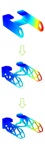
Integrating structural analysis tools with other systems enhances the overall workflow, improves data accuracy, and streamlines project management.

Many structural analysis tools offer APIs and Scripting tools that enable custom integrations with other software tools. Python, C#, and VBA are commonly used for scripting the integration between tools, automating workflows, and ensuring seamless data exchange. Custom scripts can automate the transfer of data (e.g., model parameters, loads, or analysis results) between software, reducing manual work and minimizing errors.

Cloud-Based Platforms facilitate collaboration in real-time by providing a shared environment for storing and updating project data ensuring everyone works with the most up-to-date information.

Applications of Structures

Aerospace and Automotive

Structural integrity of the body.

Heavy Industrial Equipment

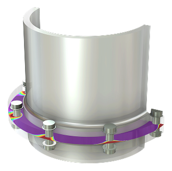
Large pressure vessels, tanks, and reactors.

High-Performance Materials

Composite structures and advanced alloys.

Medical

Stents and other medical devices.

Railways

Structural analysis for railway systems.

Naval Structures

Design and analysis of marine vessels.

Power Generation

Structural integrity in power plants.

Thermal

Problem Statement

"Given the increasing demand for high-performance materials and systems in industries such as aerospace, automotive, electronics, and civil engineering, there is a critical need to analyze and predict the thermal behavior of components and structures under a wide range of temperature conditions. The challenge is to understand how temperature variations—due to internal and external sources such as mechanical forces, heat generation, environmental conditions, and operational processes—affect the material properties, structural integrity, and overall performance of these systems."

thermal

Solution Summary

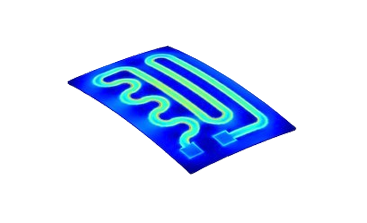
Efficient thermal management is crucial for the optimal performance and longevity of systems across industries, from electronics and automotive to energy and manufacturing. Accurately simulating and managing heat flow, thermal distribution, and temperature effects helps ensure that components operate safely and effectively in various conditions. Our advanced thermal simulation solutions empower engineers to model, analyse, and optimize thermal systems for enhanced performance, energy efficiency, and durability.

Thermal Management Benefits

Benefits

  • Improved Safety and Reliability: Predicts thermal behavior, minimizing risks like overheating, freezing, or thermal expansion.
  • Cost Savings: Optimizes heat management, reducing the need for costly cooling systems and avoiding overdesign.
  • Efficiency in Design: Speeds up development by allowing quick iterations and simplifying complex thermal effects.
  • Customization and Flexibility: Tailors thermal solutions to specific materials, geometries, and systems, while adapting to design changes.
  • Better Sustainability: Enhances energy efficiency, reduces material waste, and extends product lifespan.

Our Approach

How it Works

  • Define the Problem
    • Understand the thermal conditions that a component or system will be exposed to, such as heat sources, temperature boundaries, and thermal loads.
  • Create a Model
    • Simplify the geometry of the system, considering both steady-state and transient heat transfer effects. Define the thermal properties of materials involved.
  • Apply Thermal Loads and Boundary Conditions
    • Specify the sources of heat and heat transfer conditions, such as conduction, convection, and radiation, along with thermal boundary conditions like temperature gradients or fixed thermal values.
  • Choose Analysis Method
    • Select the appropriate analysis method (steady-state vs. transient, 1D, 2D, or 3D analysis) based on the complexity of the thermal behavior being studied.
  • Formulate and Solve Equations
    • Use heat conduction, convection, and radiation equations (Fourier’s Law, Stefan-Boltzmann Law, etc.) to calculate temperature distribution, heat flux, and thermal stresses within the system.
  • Post-Processing
    • Analyze the results of the thermal analysis, such as temperature distribution, thermal gradients, and potential points of thermal failure (hot spots, thermal expansion).
  • Optimize Design
    • Refine the design to ensure that it meets thermal performance criteria, reduces energy consumption, and optimizes material selection to withstand high temperatures or thermal gradients.
  • Verify and Validate
    • Compare the results with experimental or analytical results to verify the model’s accuracy and perform sensitivity analyses to ensure robustness under varying thermal conditions.
  • Final Design
    • Generate detailed documentation and analysis reports for final approval, including temperature profiles, material specifications, and performance under thermal loading.

Key Features

Thermal Load Types

Handles steady-state and transient thermal loads, including heat conduction, convection, and radiation models.

Material Properties

Considers thermal conductivity, specific heat, and temperature-dependent behavior, including phase changes.

Boundary Conditions

Defines fixed temperatures, heat fluxes, and temperature-dependent boundaries for accurate thermal modeling.

Analysis Types

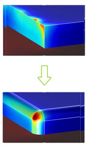
Supports steady-state, transient, and thermal stress analyses to study temperature effects on structures.

Accuracy Requirements

Ensures mesh refinement, numerical stability, and convergence checks for precise temperature predictions.

Compliance with Standards

Adheres to thermal analysis codes and regulations like ISO, ASME, or ASTM for safety and performance.

Verification

Compares results with known solutions, experimental data, or analytical models for model accuracy.

CFD

Problem Statement

In engineering and design, the challenge is to accurately predict and optimize the behavior of fluids within complex systems—ranging from airflow over aircraft wings to heat dissipation in electronic devices and water flow in piping systems. The problem lies in understanding how fluids interact with structures, how energy is transferred between fluid layers, and how various forces (e.g., turbulence, viscosity, thermal gradients) influence the flow and system efficiency under varying operational conditions. The goal is to simulate and predict these fluid behaviors in a computationally efficient manner, ensuring that the design performs optimally while minimizing energy consumption, material use, and environmental impact.

CFD Challenges

Solution Summary

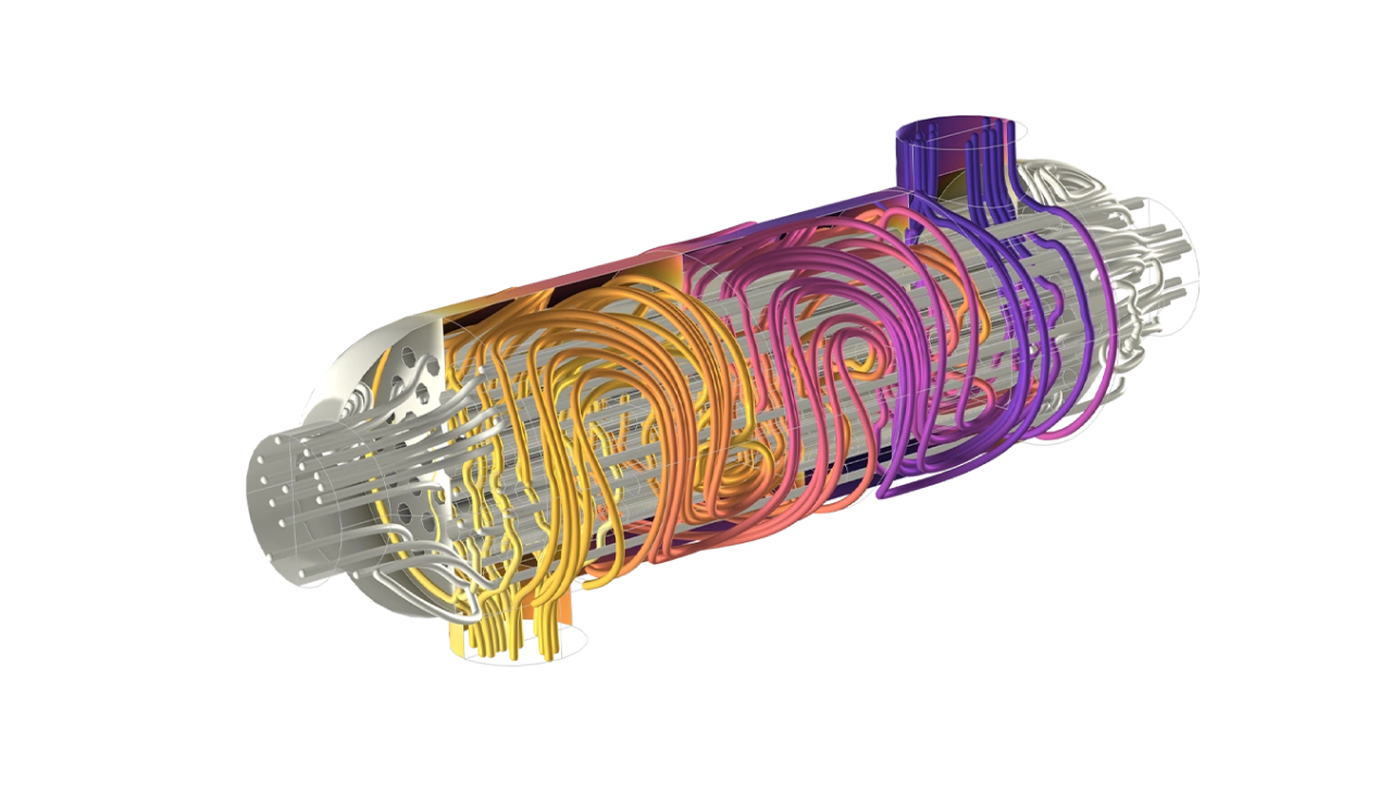
Fluid dynamics plays a pivotal role in optimizing designs for various industries, from automotive and aerospace to energy and HVAC systems. Accurate simulation of fluid flow, heat transfer, and multi-phase interactions ensures that systems are efficient, safe, and optimized for real-world conditions. Our Computational Fluid Dynamics (CFD) solutions provide engineers with powerful tools to model and analyse fluid flow, temperature distributions, and complex thermal effects to enhance performance and reduce operational costs.

Fluid Dynamics Benefits

Benefits

  • Improved Safety and Reliability: Predicts fluid behavior to assess safety and identify issues like turbulence or pressure drops before they occur.
  • Cost Savings: Reduces the need for physical prototypes and optimizes performance to minimize operational costs.
  • Efficiency in Design: Speeds up development with rapid iterations and simulates complex fluid behaviors.
  • Customization and Flexibility: Tailors simulations to specific design needs and adapts easily to changes in design or conditions.
  • Better Sustainability: Optimizes energy use and reduces environmental impact, contributing to greener operations.

Our Approach

How it Works

  • Define the Problem
    • Identify the system or component subjected to fluid flow, including operating conditions (inlet/outlet flow, temperature, pressure) and fluid type (air, water, oil, gas).
  • Create a Model
    • Define the geometry of the system to simulate fluid flow, using a 2D or 3D representation.
  • Apply Boundary Conditions
    • Specify inlet and outlet conditions, wall boundaries, pressure boundaries, and heat transfer conditions.
  • Choose Analysis Method
    • Select appropriate solvers for flow analysis (steady-state vs. transient), turbulence models, and thermal analysis if applicable.
  • Formulate and Solve Equations
    • Use the Navier-Stokes equations, continuity equation, and momentum equations to solve for fluid properties.
  • Post-Processing
    • Analyze results including velocity fields, pressure distributions, temperature gradients, and critical parameters.
  • Optimize Design
    • Refine the design based on CFD results to improve performance metrics such as drag, heat transfer, or fluid distribution.
  • Verify and Validate
    • Compare CFD results with experimental data or analytical solutions to ensure model accuracy.
  • Final Design
    • Generate detailed reports summarizing CFD results, including visualizations and performance metrics.

Key Features

Fluid Flow Simulation

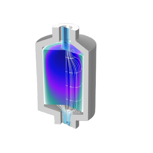
Simulates fluid flow, analyzing velocity, pressure, and turbulence.

Turbulence Modeling

Offers turbulence models (e.g., k-ε, LES) for complex flows.

Multi-Phase Flow

Supports multiphase fluid simulations with surface tension and phase changes.

Heat Transfer Analysis

Models heat transfer via conduction, convection, and radiation for thermal management.

Combustion Modeling

Simulates combustion processes, including chemical reactions, emissions, and flame dynamics.

Mesh Generation

Provides structured and unstructured meshes, with adaptive mesh refinement for improved accuracy in critical regions.

Fluid-Structure Interaction (FSI)

Simulates fluid-structure interaction, including deformable boundaries and flow-induced vibrations.

Multi-Physics Simulations

Combines fluid dynamics with heat transfer, electromagnetics, and acoustics for complex analyses.

Acoustics

Problem Statement

Sound plays a critical role in product performance, safety, and user experience across industries—from automotive to consumer electronics. Accurately predicting how sound waves travel through air, fluids, and solids, and how they interact with materials, structures, and flows is complex. Engineers must account for reflections, resonance, absorption, and even structural coupling. Without accurate simulation, designs risk noise issues, inefficiencies, or costly redesigns.

CFD Challenges

Solution Summary

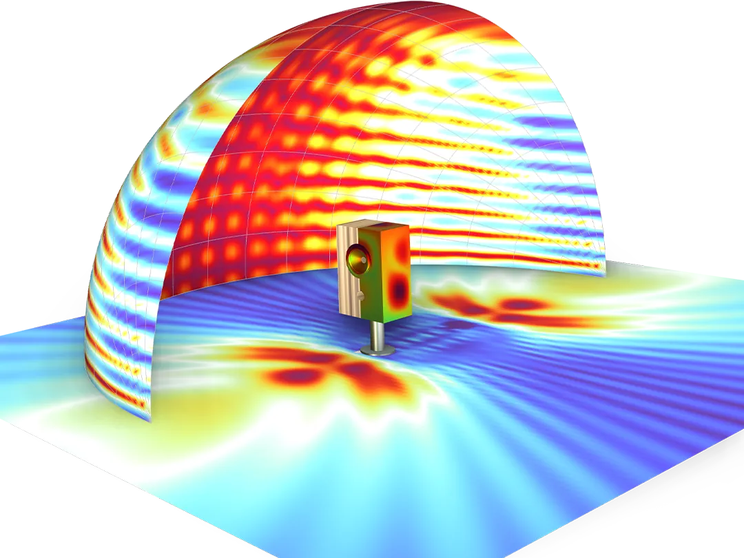
Our acoustic simulation tools are built to handle real-world complexity. Whether you're designing a quiet car cabin, a high-performance speaker, or a medical ultrasound device, we provide the tools to simulate acoustic performance accurately and efficiently. Our solutions combine advanced physics with intuitive modeling workflows to help you build better products, faster.

Fluid Dynamics Benefits

Benefits

  • Improved Accuracy: Simulate wave behavior across various materials, frequencies, and environments for more reliable results.
  • Faster Development: Cut down on physical prototyping by utilizing advanced virtual testing and simulations.
  • Design Flexibility: Easily modify models to accommodate design changes or evolving performance needs.
  • Multiphysics Integration: Model interactions between sound, structure, fluids, and thermal effects within a single environment.
  • Cost Savings: Minimize late-stage design changes and optimize material usage early in the development cycle.

Our Approach

How it Works

  • Define Objectives
    • Identify acoustic goals, frequency range, and physical domains involved.
  • Model Setup
    • Build or import geometry and assign relevant physics interfaces (e.g., pressure acoustics, structural coupling).
  • Boundary Conditions & Sources
    • Configure sources, loads, and boundary types (e.g., impedance, reflection, absorption).
  • Simulation & Analysis
    • Run simulations in the time or frequency domain using FEM, BEM, or ray tracing.
  • Post-Processing
    • Visualize sound pressure, intensity, wave propagation, and identify potential design improvements.
  • Optimization & Validation
    • Refine model parameters and validate against test data or known benchmarks.

Key Features

Automotive & Aerospace

Cabin acoustics, mufflers, jet noise, engine enclosures.

Consumer Electronics

Loudspeakers, microphones, headphones, hearing aids.

Architectural Acoustics

Room acoustics, soundproofing, duct noise.

Medical Devices

Ultrasound probes, imaging systems, diagnostic equipment.

Marine & Underwater

Sonar systems, submerged equipment, underwater communication.

Industrial Equipment

Silencers, compressors, acoustic panels.

Musical Instruments

Instrument design, soundboard tuning, resonance control.

Optics

Problem Statement

From high-precision lasers to complex imaging systems, modern optical design demands a deep understanding of how light behaves across different media and scales. Engineers must analyze reflection, refraction, diffraction, interference, polarization, and material effects—often across multiple physical domains such as heat and structural stress. Traditional methods may fall short when dealing with complex geometries or coupled physical effects, making simulation essential for efficient, accurate, and innovative optical system design.

CFD Challenges

Solution Summary

We offer powerful simulation platforms for both Wave Optics and Ray Optics, enabling accurate analysis of optical systems across different scales and applications. These tools are fully integrated into a multiphysics environment, allowing you to couple optical simulations with structural, thermal, or electrical effects to create comprehensive and predictive models.


Wave Optics Module

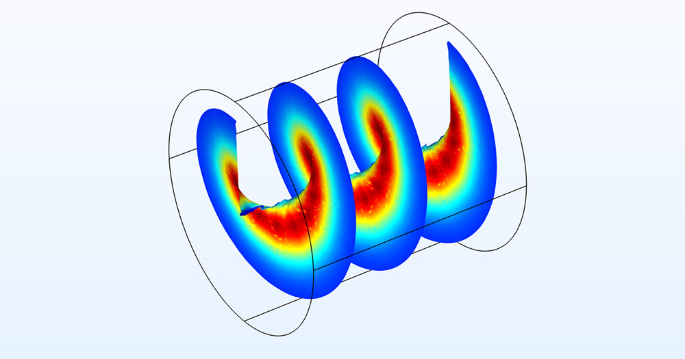
Wave Optics is ideal for analyzing light as an electromagnetic wave—capturing interference, diffraction, mode propagation, and nonlinear optical phenomena with high fidelity.

Fluid Dynamics Benefits

Benefits

  • Full Electromagnetic Modeling: Solve Maxwell’s equations directly in both frequency and time domains for precise results.
  • Beam Envelope Method: Efficiently simulate guided waves and slowly varying optical fields over large spatial domains.
  • Nonlinear Optics: Model complex nonlinear phenomena such as second-harmonic generation and Kerr effects.
  • Mode Analysis: Calculate eigenmodes in waveguides, resonators, and photonic crystals with high accuracy.
  • Material Dispersion Support: Access comprehensive libraries for refractive indices and wavelength-dependent material properties.

Key Features

Integrated Photonics & Silicon Photonic Circuits

Integrated photonics and silicon photonic circuits.

Optical Waveguides & Fiber Optics

Optical waveguides and fiber optics.

Photonic Crystals & Metasurfaces

Photonic crystals and metasurfaces.

Laser Cavity Design & Mode Control

Laser cavity design and mode control.

Nonlinear Optical Devices & Sensors

Nonlinear optical devices and sensors.


Ray Optics Module

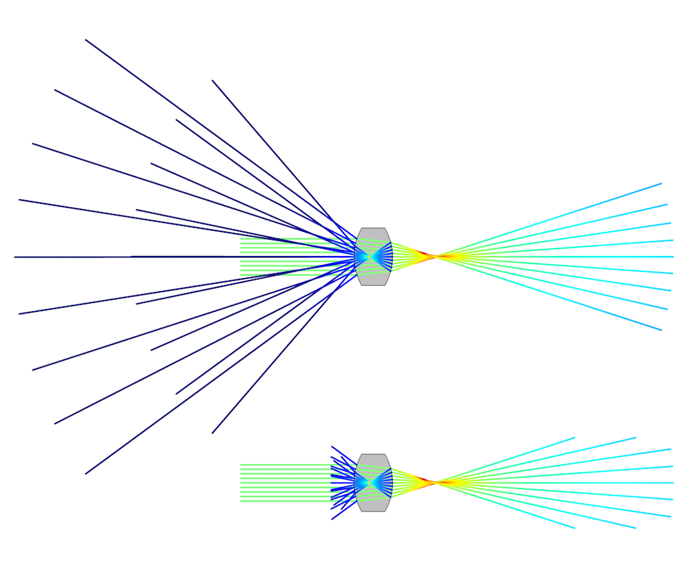
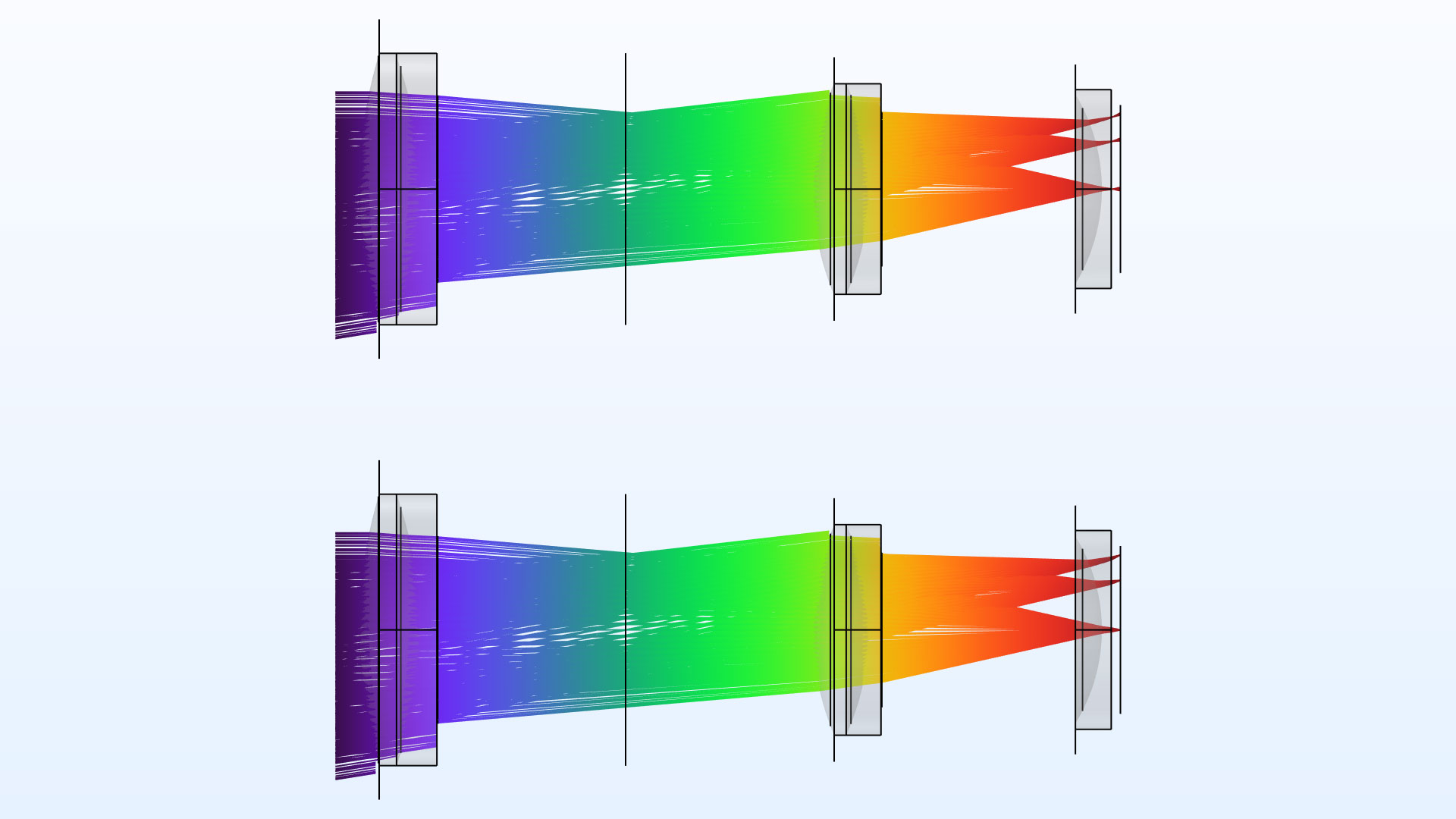
Ray Optics focuses on the geometrical behavior of light—ideal for large-scale systems where light can be treated as rays rather than waves.

Fluid Dynamics Benefits

Benefits

  • Geometrical Ray Tracing: Trace millions of rays through intricate 3D systems, with support for reflection, refraction, and absorption.
  • Polarization and Coatings: Accurately model polarization states and the effects of multilayer coatings on optical behavior.
  • Scattering and Loss: Simulate scattering, surface roughness, and material absorption for realistic optical interactions.
  • Beam Heating and STOP Analysis: Integrate optical and thermal simulations to assess laser heating, lens deformation, and stress-optic effects.
  • Spectral and Angular Analysis: Evaluate system performance across a wide range of wavelengths and incident angles.

Key Features

Integrated Photonics & Silicon Photonic Circuits

Integrated photonics and silicon photonic circuits.

Optical Waveguides & Fiber Optics

Optical waveguides and fiber optics.

Photonic Crystals & Metasurfaces

Photonic crystals and metasurfaces.

Laser Cavity Design & Mode Control

Laser cavity design and mode control.

Nonlinear Optical Devices & Sensors

Nonlinear optical devices and sensors.


Multiphysics Integration

Both optics modules support seamless coupling with other physics domains:

Thermal Effects

Model laser heating, thermal lensing, and material expansion.

Structural Deformation

Include stress-optic effects or deformation of optical components.

Electromagnetics

Combine optics with RF, microwaves, and plasmonic effects.

Scripting & Automation

Use Python®, MATLAB®, or Java® APIs for custom workflows and optimization.

Collaboration

Cloud and server tools enable team-wide access and real-time collaboration.

Contact us

For below details

  • Technical Specification Details
  • Platform Architecture
  • Integration Guide
  • Case Study Insights
  • or more


Email us at

info@Mahirut.com

Success

Thank you for your submission!

We will get back to you soon

Server error: Please try again after some time.


Solutions

Power Electronics

CAE

CAE-EMAG

CIVIL

Head Office
No 3M-211, Ground Floor, Outer Ring Road, East of NGEF Layout, Kasturi Nagar, Bengaluru - Karnataka - 560043
+91 80 61222900(30 Lines)
info@Mahirut.com
Resource

Blogs

Videos

Career

Gallery

Events

Mou’s

Follow us